CPC6314 325W DC Power Supply with IPMI Management
下載PDF
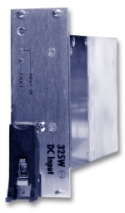 The CPC6314
Hot-Swap DC Power Supply, part of our Advanced Managed Platform product
offering, combines high power capacity with standards-based IPMI management
capability and a reliable, modular package to become the power supply of choice
for systems requiring DC power input. This CompactPCI® 3U x 8HP form factor
supply is ideally suited for telecommunications, industrial automation and a
variety of embedded computer applications where redundancy and hot-swap are
required.
The CPC6314
Hot-Swap DC Power Supply, part of our Advanced Managed Platform product
offering, combines high power capacity with standards-based IPMI management
capability and a reliable, modular package to become the power supply of choice
for systems requiring DC power input. This CompactPCI® 3U x 8HP form factor
supply is ideally suited for telecommunications, industrial automation and a
variety of embedded computer applications where redundancy and hot-swap are
required.
The input voltage range is -36 to -72VDC. Four outputs are capable of
providing a total of 325W for +3.3VDC, +5VDC and ?12VDC with independent output
regulation. This supply implements management functions such as system control,
monitoring and status reporting through an IPMI-based intelligent communications
bus. The CPC6314, meets the electrical and mechanical requirements of the PICMG®
specification for CompactPCI systems. It uses a 47-pin Positronic power
connector to provide efficient, effective, high current DC connectivity and is
UL, CSA, IEC recognized TUV CB Certificate and CE Marked.
The ZT 6303 250-Watt Hot-Swap Power Supply is available as an AC alternative.
Highlights
- 325W output power
- Hot-swap, N+1 load sharing
- 47-pin input/output connector
- Protection features
- Input fusing
- Input reverse polarity
- Overvoltage
- Overcurrent/short circuit-auto recovery, all outputs
- Overtemperature warning and shutdown
- Fault isolation
- IPMI-compliant system management functions
- Status LEDs-fault, input OK
- Status output signals-(DEG#), (FAL#)
- Main output remote sense (+3.3V, +5V, +12V)
- Built-in EMI filter
- Eurorack-compatible module
- Injector/ejector handle
Key Design Elements
Operation
The CPC6314 325W power supply utilizes switching technology to achieve its
small size and large power output. An EMI-filtered input automatically accepts
DC input voltages from -36 to -72VDC. Optionally, two or more power supplies can
be used to implement an N+1 or N+N, load sharing, fault-tolerant system. An
optional I2C hardware bus interface supports IPMI protocol for use in systems
compliant with the PICMG 2.9 R1.0 specification.
Load Sharing and N+1 Redundancy
Two or more power supplies can share the same input source. With two
supplies, each provides approximately 50 percent of the total system power
during normal operation, although either is capable of powering the entire
system (with a 325W load) in the event that the other should fail. This feature
increases overall system reliability by sharing the load responsibilities.
Additional power supplies may be used to implement true N+1 load sharing (i.e.,
a 650W system requires two power supplies, plus a third for redundancy).
Hot-Swap and Fault Tolerance
The CPC6314 power supply can be inserted or removed from a system employing a
redundant power scheme without disturbing operation or reducing the reliability
of any associated devices. Likewise, a failed power supply will not disturb the
operation of the system if a redundant power supply is operating in the system.
Status LEDS
Two status LED indicators are visible from the front of the power supply. The
green “INPUT” LED indicates that the input voltage is present. The green “INPUT”
LED blinks when the power supply outputs are inhibited. Off indicates no input
power is present. The amber “FAULT” LED indicates a failed power supply or input
source.
Remote Sense
Remote sense on the +3.3V, +5V and +12V power supply outputs detects the
voltages at a load remote from the power supply, compensating for connector,
backplane and wiring voltage drops >0.25V.
Inhibit/Enable Inputs (INH#, EN#)
The INH# input signal on the rear connector turns off the outputs when
grounded. EN# is used in conjunction with INH# to enable the power supply after
all signals make contact with the mating connector. Outputs are disabled as the
EN# pin is disengaged.
The source into a grounded connection is <150mA and the open circuit input
voltage shall be <+15VDC. The signal is capable of sinking >2mA and maintaining
the output voltage at <0.5VDC.
Current Share
Active current sharing is provided on the +3.3V, +5V and +12V power supply
outputs with accuracy better than 10 percent of maximum rated load with up to
eight supplies operating in parallel. Passive (droop response) current sharing
is provided on the –12V output.
System Notification (DEG#, FAL#)
Two fault outputs are available on the rear connector for system
notification. One output (DEG#) is an open collector/drain, low true signal that
indicates the internal temperatures are within 10 (degrees) C of the thermal
shutdown limit. The second output (FAL#) is an open collector/drain, low true
signal that indicates when the supply has shut off the outputs due to a problem
or the input voltage has been removed.
Overvoltage Shutdown
A 125 percent of nominal overvoltage condition on any of the outputs disables
all outputs of the power supply. Outputs can be enabled, once the overvoltage
condition is resolved, either with an IPMI command or by cycling the input power
of the system.
Overtemperature Shutdown
The power supply automatically shuts down if an overtemperature event occurs.
Overtemperature events causing a shutdown include a hardware-defined trip point
or a trip point defined through an IPMI command. Once the supply cools down the
supply restarts automatically.
Geographical Address Pins (GA0, GA1, GA2)
These pins configure the final IPMI address for the power supply. The
geographical address pins are pulled up to +5VDC via a 10KW±10 percent resistor
on each signal.
IPMI Interface
The CPC6314 provides an I2C hardware bus interface that supports IPMI
protocol consistent with PICMG 2.9 R1.0. The IPMI controller is an event
generator and is implemented as a dynamic SDR device.
The following sensors are supported:
• Temperature sensor(s) of critical areas
• DEG# thermal warning status
• FAL# signal status
• Output voltages (+3.3V, +5V, +12V, -12V) on the inboard side of the output
isolation device with a resolution of 1 percent and an accuracy of ±2 percent
• Output currents with a resolution of 500mA and an accuracy of ±10 percent
The following functions are supported:
• IPMI controller reset
• Position (geographic) address
• Field Replaceable Unit (FRU) information
• Fault LED control commands
• Firmware upgradeable through the I2C bus
Specifcations
The CPC6314 is compliant with the following specifications:
• CompactPCI Core Specification, PICMG 2.0 R2.1
• CompactPCI Power Interface Specification, PICMG 2.11 R1.0
• CompactPCI System Management Specification, PICMG 2.9 R1.0
• Intelligent Platform Management Interface (IPMI) Specification, V1.5 Rev 1.1
and IPMB V1.0
| Hold Up Time |
2ms typical from -54VDC input |
| Electrical |
Input Voltage Range: -36 to -72VD
Input Filter Type: common and differential mode |
Environmental
|
- General: Complies with the requirements of GR- 63-CORE environmental
criteria
- Airflow: External airflow of 200lfm will be provided. The supply will
be inverted in some applications and may also be mounted horizontally.
- Operating Temperature: 0 to 50°C (0 - 70°C with linear derating of
power to 50% of rated output between 50 and 70°C); short-term operation at
55°C for 96 hours at full load will be supported.
- Storage Temperature:-20 to +85°C
- Operating Altitude: Up to 13,000 feet (with ambient derating above
6,000 feet equal to the adiabatic lapse rate - approximately 2°C per 1,000
ft.)
- Non-Operating Altitude: up to 40,000 feet
- Humidity: <95% maximum, non-condensing
|
| Input Current |
Maximum Continuous: 11.5A
Cold Start, Surge Maximum: <16A max. peak, - 36 to -72VD input |
| Output Specifications |
- Total Output Power (max. continuous @ 55°C with 200 LFM): 325W
- Total Output Current:
+3.3V @ 30.0A + 4/-2% output regulation (expected to meet or exceed 20A ±2
percent)
+5V @ 40.0A + 4/-2% output regulation (expected to meet or exceed 25A, 2A
min ±2 percent)
+12V @ 5.0A +/-4% output regulation (expected to meet or exceed 5.5A ±2
percent)
-12V @1.0A +/-4% output regulation (expected to meet or exceed 0.5A ±4
percent)
|
Ripple and Noise (measured at full load with 20MHz bandwidth)
|
+3.3V 50mV max P-P
+5V 50mV max P-P
+12V 240mV max P-P
-12V 240mV max P-P |
| Overvoltage Protection (+3.3V, +5V) |
125 percent maximum |
| General Specifications |
Efficiency: 80 percent typical
Weight: 1.55 lbs (704 g) |
Reliability
|
MTTR: One minute (based on module replacement) |
| Regulatory Compliance |
Designed for NEBS/ETSI
CE Certification
The CPC6314 meets intent of Directive 89/336/EEC for Electromagnetic
Compatibility & Low-Voltage Directive 73/23/EEC for Product Safety.
Compliance was demonstrated to the following specifications as listed in the
Official Journal of the European Communities:
Safety
- UL 60950
- CSA 60950
- VDE to EN60950
- CB Report
- CE Certificate
EMI Compatibility ( DC-input model)
- ETSI 300-386, Class A
- EN55022 Radiated Emissions Class A
- EN61000-4-2 ESD (Level 4)
- EN61000-4-3 Radiated Immunity (Level 2)
- EN61000-4-8 Magnetic Field Immunity (Level 2)
Safety Agency Ratings ( DC-input model)
- Input Voltage: -36 to -75VDC
- Input Current: 11.3A
- Input Power: 406W
- Isolation:
- 1500VDC primary-secondary
- 1500VDC primary-chassis
- 500VDC secondary-chassis
|