Product Description |
|
The M97 is based on the M-Module ANSI mezzanine
standard. It can be used as an I/O extension in any type of bus system, i.e.
CPCI, PXI, VME or on any type of stand-alone SBC. Appropriate M-Module
carrier cards in 3U, 6U and other formats are available from MEN or other
manufacturers. |
Technical Data |
|
Basic Features |
100-MHz counter technology 32 bits resolution (9 1/2 digits) 6 measuring functions Programmable switching points and
hysteresis |
|
Measurement Functions |
Frequency (line A) High time Low time Period Totalize (line A) during external
gate (line B) Time difference (line A to B) |
|
Input Characteristics (A to B input) |
2 input lines Input voltage range Maximum input voltage if no
further safety measures are taken: Sensitivity: programmable in steps
of Minimum pulse duration: 10ns Input noise: < 100µV typ. Coupling: AC or DC (programmable) |
|
Frequency A |
Resolution: measuring time 10ns @
±1 LSB Measuring times: programmable in
steps of 1ms |
|
High time, Low time, Period |
Range: 42s Resolution: 10ns @ ±1LSB |
|
Totalize |
Gate by line B Maximum pulse duration: 42s Resolution: 10ns @ ±1LSB Gate error ±10ns |
|
Time Difference |
Maximum time difference: 42s Resolution: 10ns @ ±2LSB |
|
Time Base |
Frequency: 1kHz, based on 100MHz
system clock Time range: 1ms..32.767s Resolution: 1ms @ ±10ns |
|
Peripheral Connections |
Via front panel on a 5-pin DBM
5W5S D-Sub connector with two high-voltage contacts and two coax contacts by
FCT Via carrier board using 24-pin
connector (rear I/O) |
|
M-Module Characteristics |
A08, D16, INTA, IDENT |
|
Electrical Specifications |
Isolation voltage (inputs): 500V
DC Absolute maximum input voltages: Supply voltage/power consumption:
+5V (4.85V..5.25V), 750mA MTBF: tbd. @ 50°C |
|
Mechanical Specifications |
Dimensions: conforming to M-Module
Standard Weight: 120g |
|
Environmental Specifications |
Temperature range (operation): Temperature range (storage):
-40..+85°C Relative humidity (operation):
max. 95% non-condensing Relative humidity (storage): max.
95% non-condensing Altitude: -300m to + 3,000m Shock: 15g/0.33ms, 6g/6ms Vibration: 1g/5..2,000Hz |
|
Safety |
THE M97 DOES NOT COMPLY WITH THE
REQUIREMENTS OF THE EN60950 STANDARD. THE MAXIMUM INPUT VOLTAGES ARE 60V DC
AND 42V AC. HOWEVER, THE M97 WAS DESIGNED TO PROVIDE HIGH-VOLTAGE
FUNCTIONALITY. IF YOU NEED TO APPLY VOLTAGES HIGHER THAN 60V DC AND 42V AC,
TAKE APPROPRIATE MEASURES TO KEEP THE SAFETY REQUIREMENTS OF EN60950. PCB manufactured with a
flammability rating of 94V-0 by UL recognized manufacturers |
|
EMC |
Tested according to EN 55022 /
1999-05 (radio disturbance) and EN 55024 / 1999-05 (immunity) with regard to
CE conformity |
|
Software Support |
MEN Driver Interface System (MDIS
for Windows, Linux, VxWorks, QNX, RTX, OS-9) |
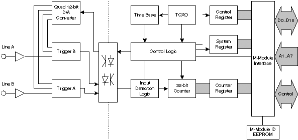
Diagram |

Related Products & Downloads |
|
Standard Hardware |
|
|
|
M97, M-Module, universal counter, closed metal housing, 0..+60°C |
|
|
M97, M-Module, universal counter, closed metal housing, -40..+85°C |
|
|
M97, M-Module, universal counter, open metal housing, 0..+60°C |
|
|
M97, M-Module, universal counter, open metal housing, -40..+85°C |
|
M-Modules with closed metal housings can only be used on
carrier cards without the 24-pin board-to-board M-Module connector, i.e. 6U
carrier cards without rear I/O connection (VME P2, CPCI J4/J5). Please order
your carrier cards accordingly! |
|
|
Please refer to our M-Module compare chart for a selection of
further instrumentation functions. |
|
|
Accessories |
|
|
|
25 mounting screw sets to fix M-Modules on carrier boards |
|
|
5W5 D-Sub plug connector, 3 high-voltage plug contacts, 2 coaxial 50-Ohm plug contacts |
|
Software |
|
|
|
MDIS4/2004 low-level driver sources for M97 |
|
|
MDIS4/2004 Windows® NT4/W2K driver for M97 |
|
|
|
|
Documentation |
|
|
|
M-Module draft specification, Rev. 3.0 |
|
|
M97 user manual |
|
|
Application Note: MDIS4 under LabWindows®/CVI |